For a fixed-wing Unmanned Aerial Vehicle (UAV) equipped with a gimbaled
camera, we consider the problem of tracking a visual target while
simultaneously bringing the UAV to orbit on a circular trajectory
centered above the target. Our objective is to achieve this kind
of loitering behavior with a feedback controller that
requires image+proprioceptive data only - and can therefore be used in
GPS-denied environments.
To solve the problem, we adopt an
Image-Based Visual Servoing (IBVS) approach. In particular, it is first
shown that regulation of the visual features plus the pan angle to a
suitable set-point entails convergence to the desired kind of
trajectory; then, such regulation is achieved for a simplified model of
the UAV+camera system with direct yaw control; finally, the same
behavior is obtained for the original
UAV+camera system through backstepping. Improvements to the basic
scheme are possible, including the enforcement of a desired radius for
the circular trajectory, a simplified roll control technique, and the
integration of an estimator to make sure that the depth of the visual
target is not needed for implementation.
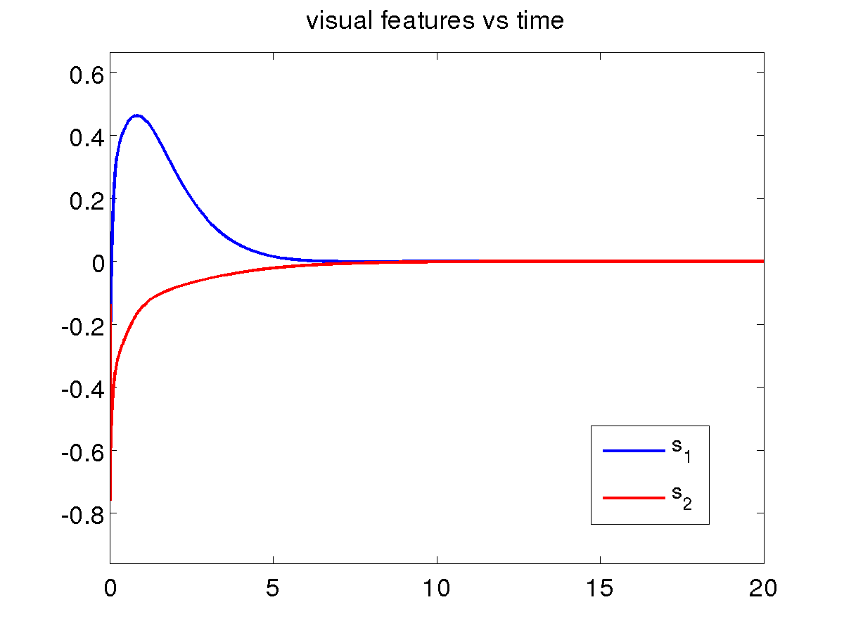
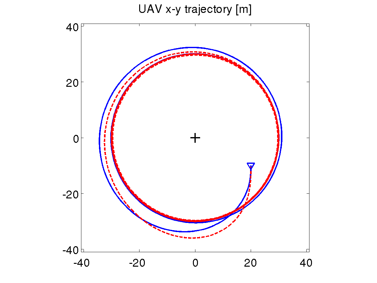
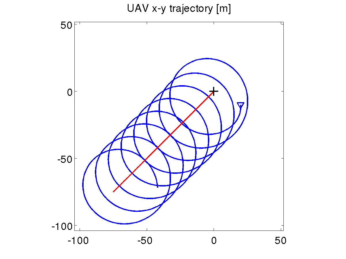
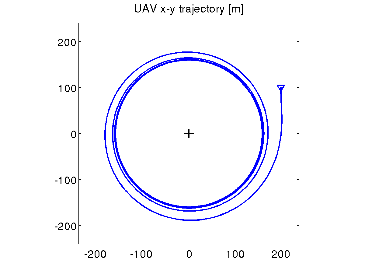
Basic loitering scheme
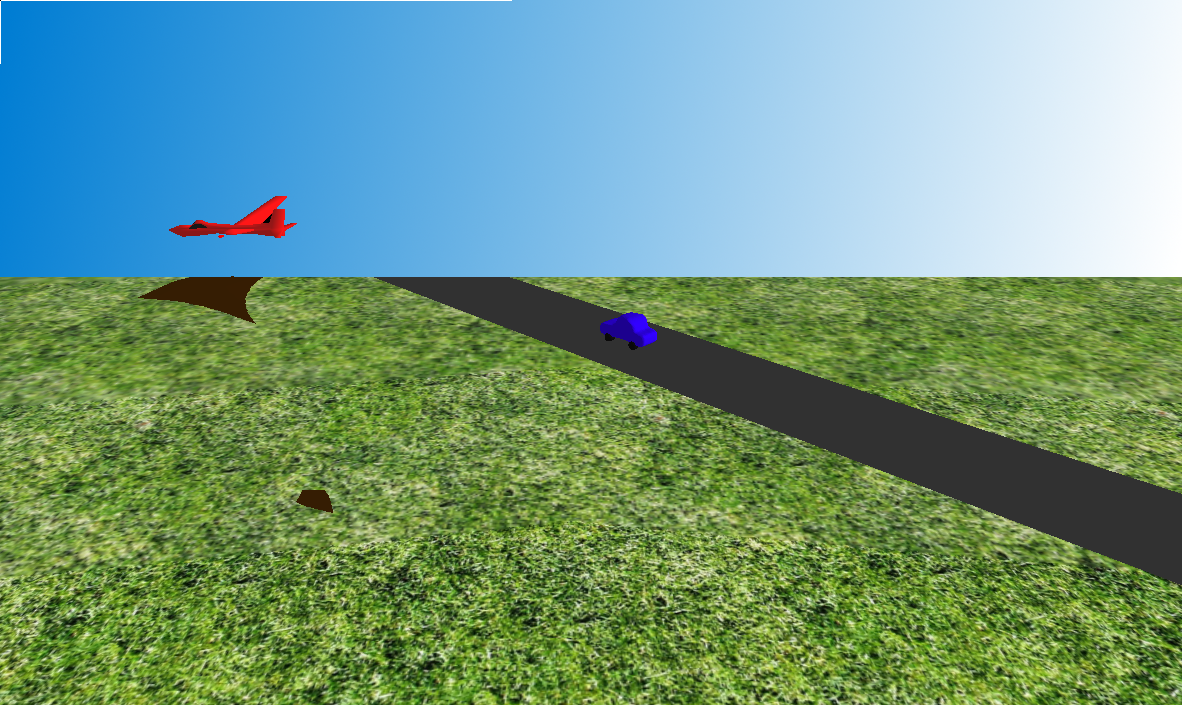
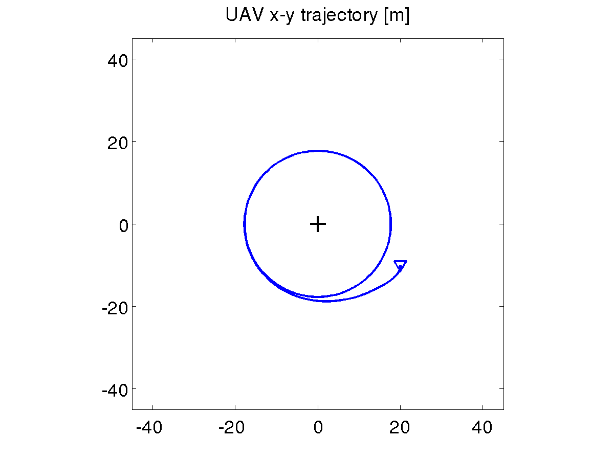
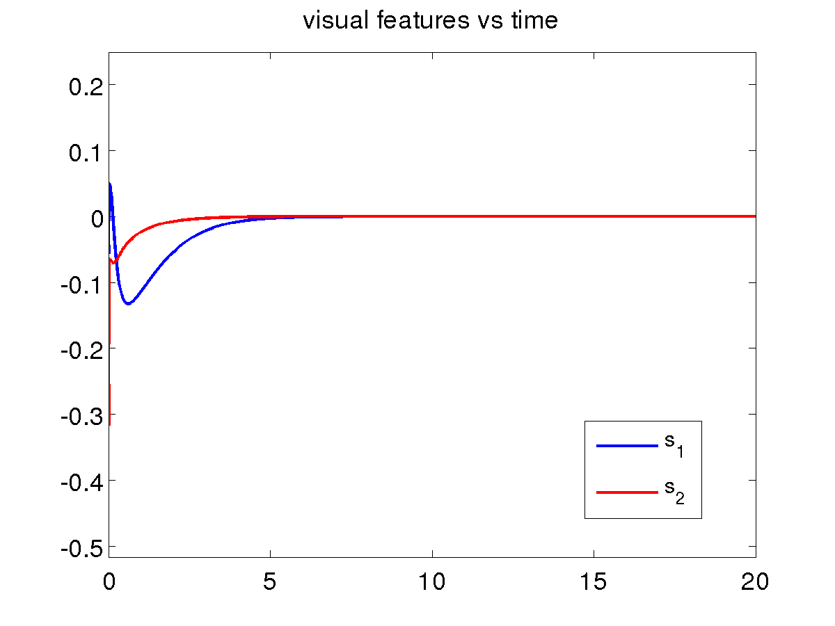
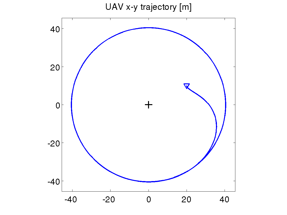
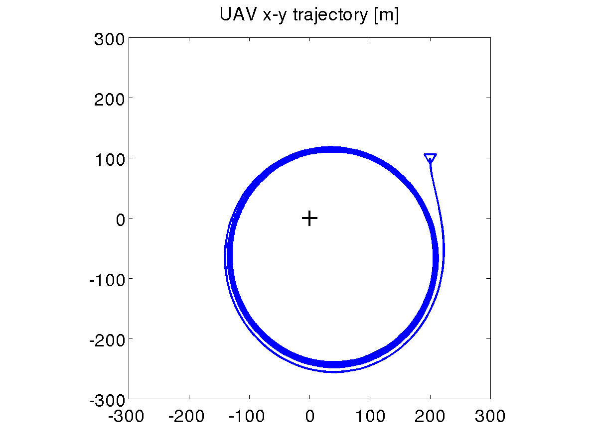
A preliminary validation of the visual loitering scheme has been
performed with the aid of MATLAB simulations. The UAV is assumed to be
in horizontal flight with a constant cruise speed of 10 m/s. The
target on the ground is indicated by the crosshair. As expected,
convergence to a circular trajectory is achieved with perfect tracking
of the target. Two simulations are shown below, corresponding to
different initial conditions.
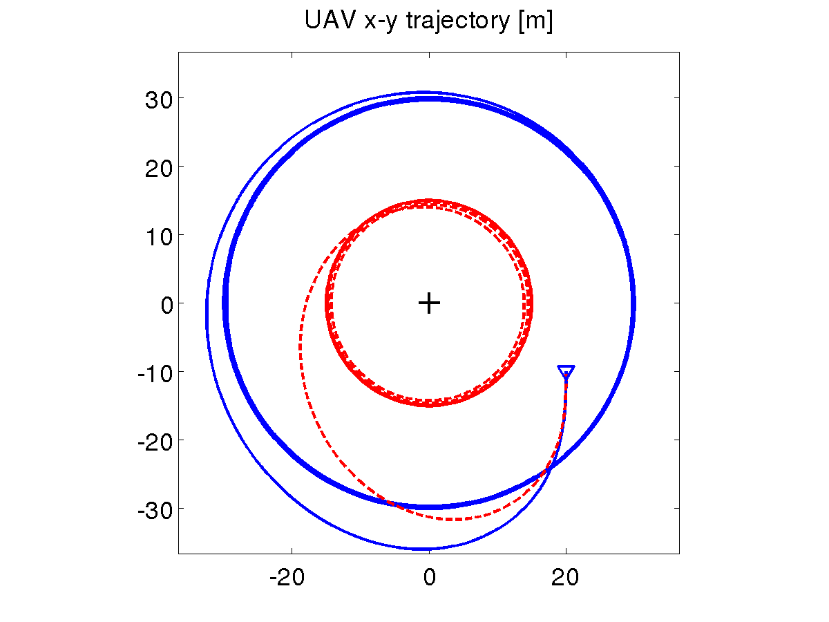
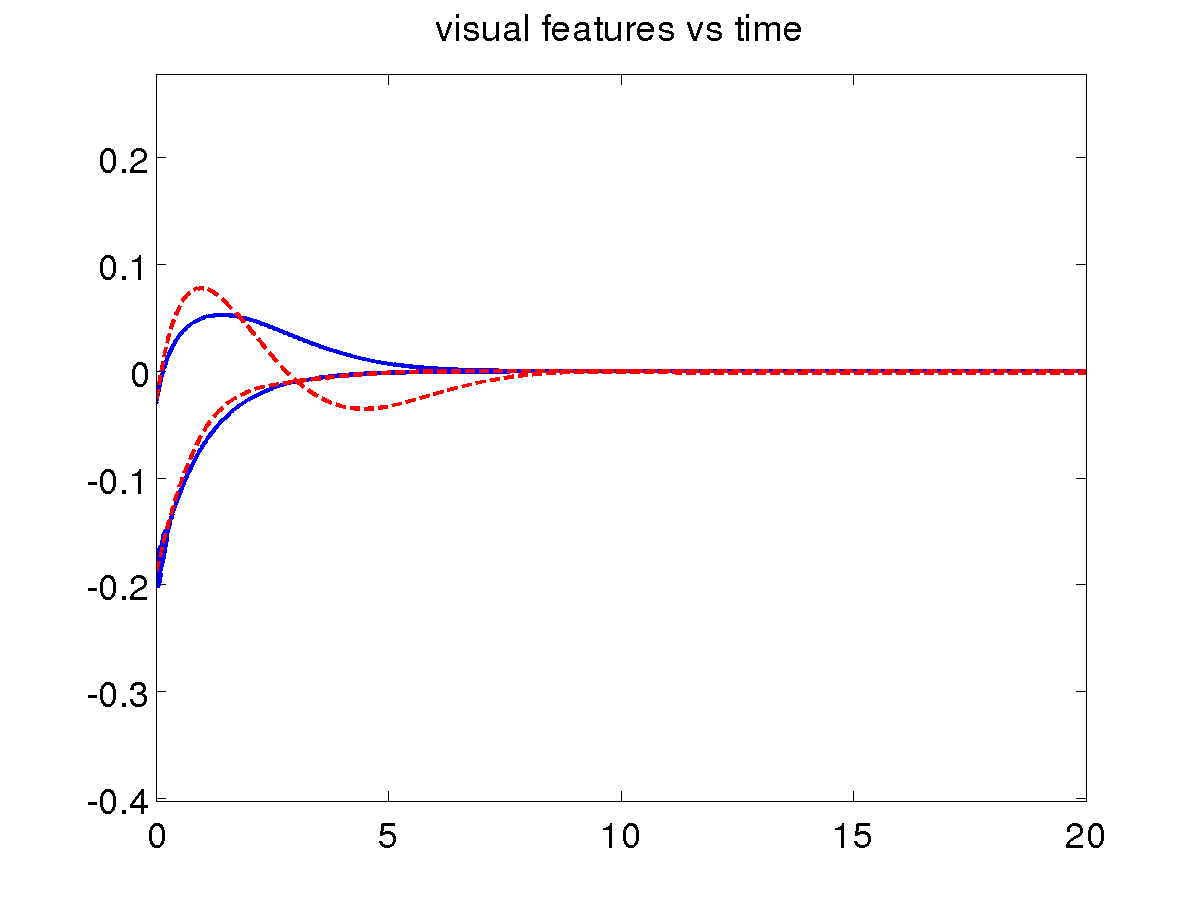
Loitering with a specified radius
The desired radius can be imposed by
adding a suitable feedforward term to the yaw control of the simplified
UAV+camera system. To make room for this, we modify our control
approach in a task-priority sense. The results are shown below,
where the UAV+camera system is driven from the same initial condition
to two different circular trajectories, with radius 30 (solid blue) and 15 (dashed red) m, respectively.
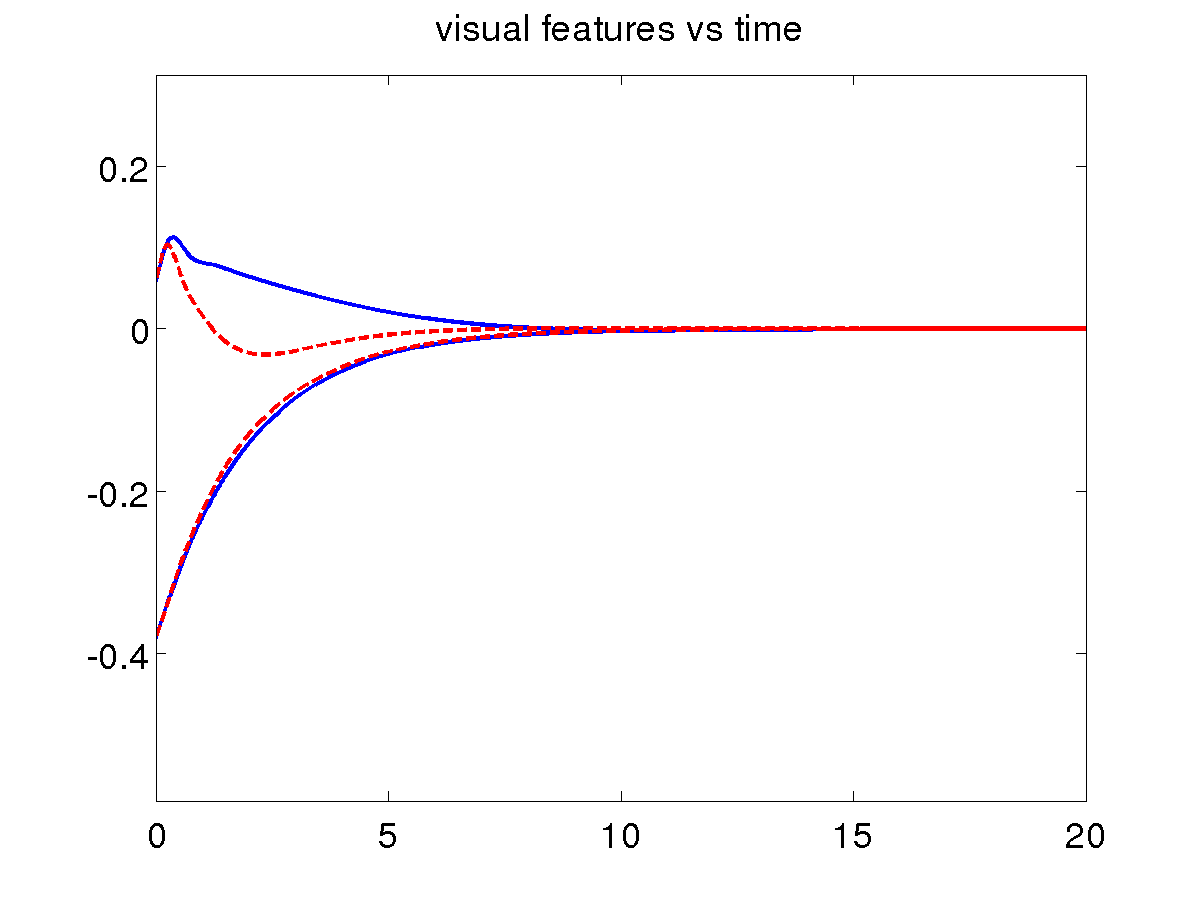
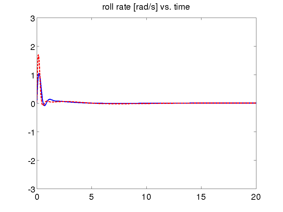
Using linear roll control
As an alternative to the backstepping approach, a simple linear roll controller can be used to guarantee that the original UAV+camera system tracks the simplified model. This more intuitive design is obviously much easier to implement, and offers similar performance (solid blue: using the linear roll controller; dashed red: using the backstepping roll controller).
Using a depth estimator
The above visual loitering method (in all its versions) needs the
feature depth for computing the interaction matrix. In principle, the
depth could be computed from the configuration of the UAV+camera
system, including the UAV cartesian coordinates, and the cartesian
coordinates of the target. This is in fact the method used in the above
simulations. However, our control approach has been to avoid altogether
the use of cartesian information, which may be indeed unavailable. A
possible solution is to estimate the depth from the evolution of the
visual features during the motion, using the nonlinear observer
described here.
The results shown below (solid
blue: using the estimated depth; dashed
red: using the actual depth) confirm that the integration of
such a component in our scheme is effective.
Moving target
The proposed visual loitering scheme performs satisfactorily also in the case of a slowly moving target. In this simulation, the target is moving at around 0.7 m/s (-0.5 m/s along x and -0.5 m/s along y) while the UAV airspeed is 10 m/s.
Video clips
Here is a video clip showing the simulations for the basic loitering scheme (fixed target) and for the moving target case.
Simulation on an Aerosonde UAV
We present a realistic simulation which shows the performance of our
visual loitering method (including all the three modifications above) on
a more complete UAV model. In particular, we have used the simulator of
the Aerosonde UAV included in
the Aerosim Blockset (formerly available here). To this accurate
simulator, which includes aerodynamic effects, we have added low level
control loops aimed at improving the adherence of the model to the
simplified model used for control design. In particular, airspeed and
altitude hold control modes have been implemented via the control of
elevator and throttle. The roll rate reference produced by the
loitering controller is tracked using a linear control loop on the
ailerons, while the rudder is used to achieve coordinated turn with
sideslip angle close to zero.
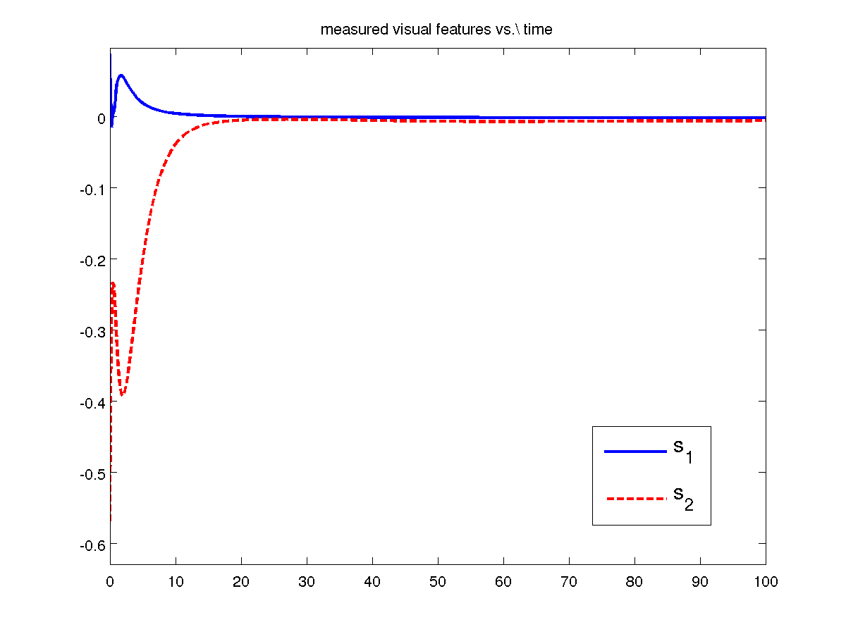
We have performed several simulations for the case of a fixed target.
The results shown below confirm that here proposed visual loitering
scheme is effective even for realistic models of UAVs.
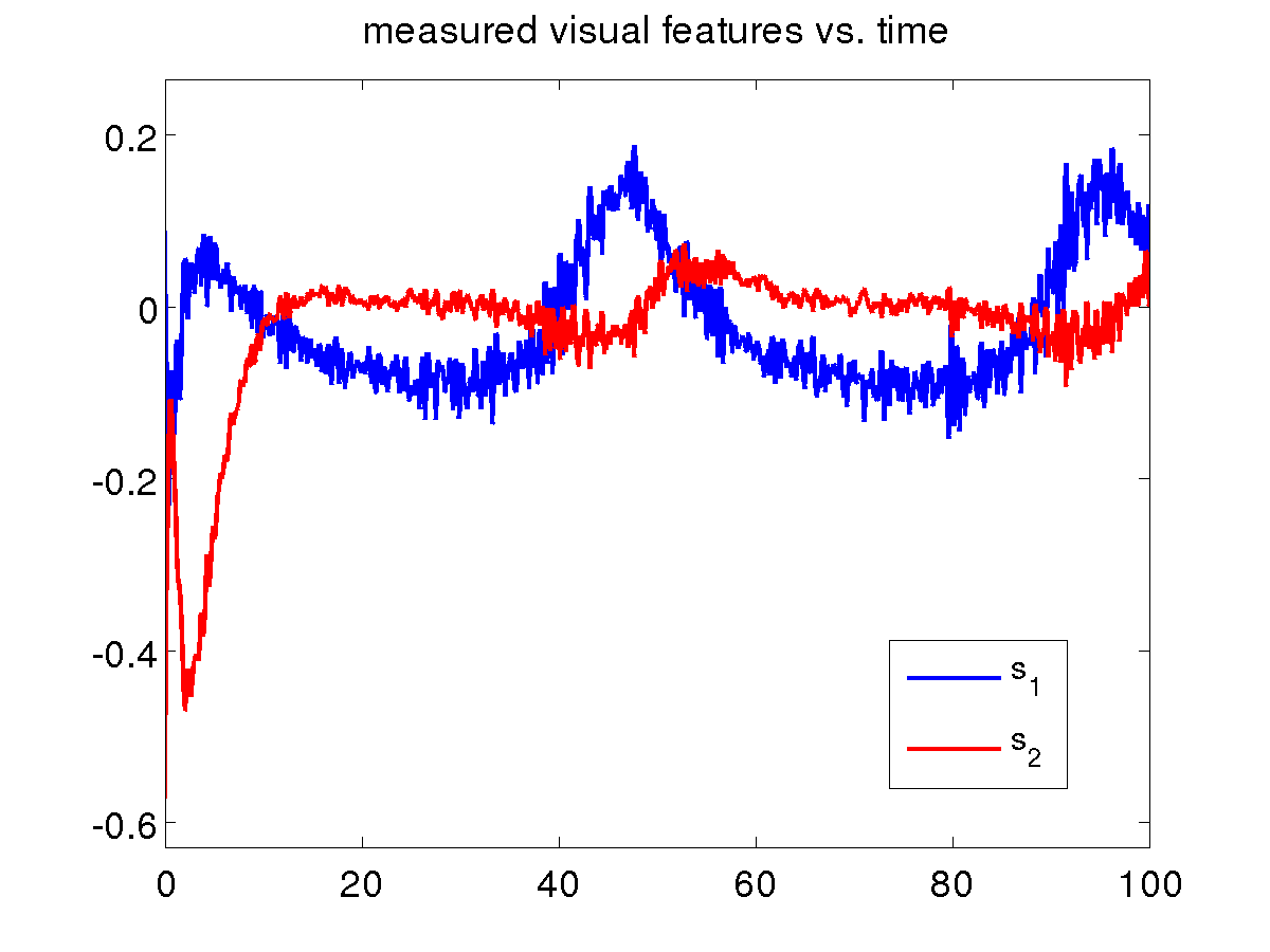
To test the robustness of the
proposed visual loitering method, we run the same Aerosonde simulation in the presence of perturbations. In particular, we added a zero-mean Gaussian noise with variance 0.01 on each visual feature and a constant wind of 8 m/s along the x axis (about 30% of the aircraft speed). The resulting trajectory is slightly deformed (and not centered on the target anymore), but the visual loitering scheme is still effective. The results are shown below.
[1] P. Peliti, L. Rosa, G. Oriolo and M. Vendittelli, Vision-based loitering over a target for a fixed-wing UAV, 10th IFAC Symposium on Robot Control (SYROCO 2012), Dubrovnik, Croatia, pp. 51-57, 2012. (pdf)